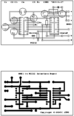
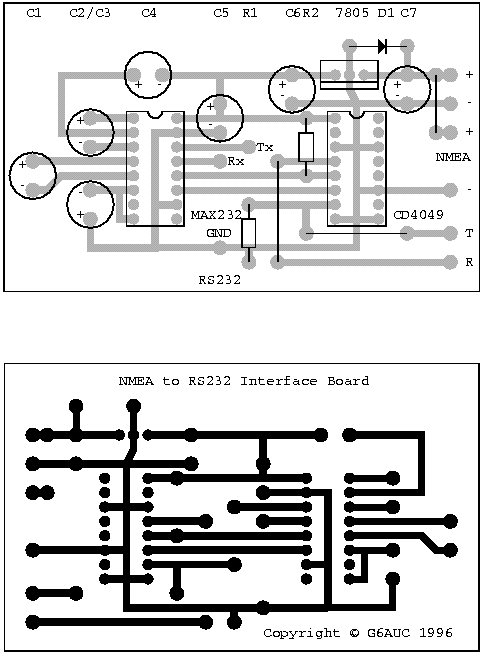
This design is based on that of Andrew Bruno. His design appeared under the name of "bruno-if". My contribution was to provide Postscript files for a Printed Circuit Board.
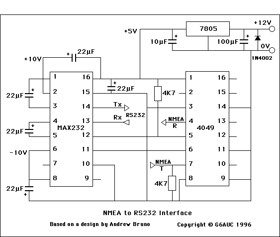
This circuit is quite old and goes back to the days of NMEA-0180 and 0182. Note that it is non-inverting. Its purpose was to shift the NEMA voltage levels to be RS232 compliant.
Many early GPS units were not fully RS232 compliant, in the sense that they did not produce a negative voltage level. The voltages were at TTL levels, but in the same sense as RS232:
5V corresponding to RS232 +10V
0V corresponding to RS232 -10V
Although not fully compliant, this meant that a GPS unit could be directly connected to many computer RS232 interfaces, but not to those that required the negative voltage.
This circuit is a level converter to produce compliant RS232 signals; it converts +5V to +10V and 0V to -10V.
Both the MAX232 and the CD4049 have inverting gates, so the total effect is a non-inverting level change.
If your NEMA signals are inverted, then you should use the pin-compatible CD4050 Hex Non-inverting Buffer, instead of the CD4049.
The circuit should be provided with a 12V DC supply using suitable wire and fuses. The circuit probably draws less than 20mA.
NMEA-0183 recommends that a talker output should have EIA-422 differential outputs and that the input circuit should use an opto-isolator with suitable protection circuitry. I cannot, therefore, recommend the use of this circuit with NMEA-0183 compliant equipment.

ICs:

MAX232CPE       RS232/TTL Interface
CD4049UBE       Hex Inverting Buffer
L7805C          5 Volt regulator

Capacitors:

C1,C2,C3,C4,C5  22 microfarad  (electrolytic - 16 volt working)
C6              10 microfarad  (electrolytic - 16 volt working)
C7              100 microfarad (electrolytic - 16 volt working for 12 volts in)
                               (electrolytic - 50 volt working for 40 volts in)
Resistors:

R1,R2           4K7 ohm (4700 ohm)

Diode:

D1              1N4002 Power Diode
Two Postscript files are provided. They can be printed directly or used as EPS files. When used as EPS files, they should not be subject to any further scaling.
NMEAx1.eps contains both the pcb design (copper side) and an overlay design, both at full scale.
NMEAx2.eps contains both the pcb design (copper side) and an overlay design, both at twice full scale.
The Postscript files and the designs are Copyright © Harry Whitfield, 1996.
Permission is hereby granted for non-commercial use.
You use the designs entirely at your own risk.

Copyright © Harry Whifield, 1996 17 August 1996

Copyright © Harry Whifield, 1996 17 August 1996
Page revised 16 June, 2018